Resources
Home
Step 1 - Part Creation
Before we start sketching the flexure, we note that the part is symmetric around its center. We can therefore save sketching effort by creating only one half of the flexure and create the second half by mirroring the first one.
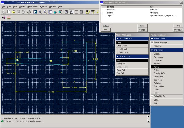
Create the basic protrusion
Using Part -> Feature -> Create -> Protrusion -> Solid sketch the shape of the right half of the flexure.
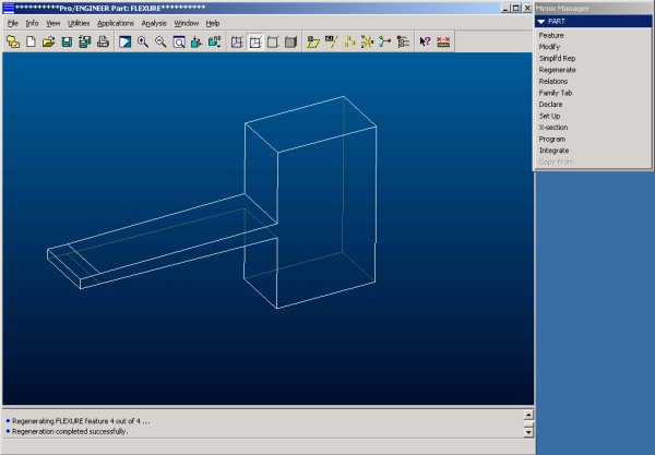
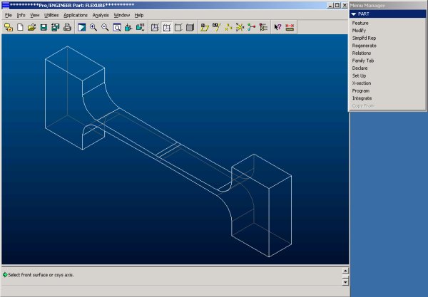
After the regeneration the extrusion will look as follows:
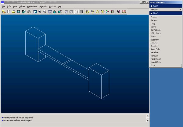
Mirror Geometry
Next we use the mirror feature to create the second half of the part. Use Feature -> Copy -> Mirror -> Dependent -> Done, then select the feature, confirm twice and select the left face as the reference plane for the mirrored feature.
Creating Rounds
The goal of this analysis is to minimize the stress within the flexure at a given displacement. A source of high stress concentration would be the sharp corner between the ends of the flexure and the beam element. To avoid this, rounds need to be created. Use Create -> Round -> Done -> Done then select the lines that mark the 4 sharp corners followed by Done and key in a value for the radius and finally hit OK.
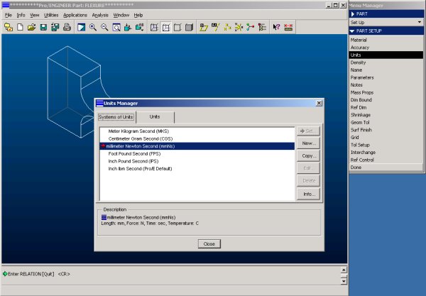
Setting Units
Pro/ENGINEER, by default, uses inches, pounds and seconds as the principal units. I personally prefer the metric system and therefore will set it to Newton, millimeters and seconds. Either system will work in Pro/MECHANICA, I suggest, however, to use the system one is most comfortable with. Use Part -> Set Up -> Units.