Resources
Home
Step 2 - Definition of Design Parameters and Relations
After the creation of the Pro/E model, identify dimensions that are crucial to the functionality of the designed part, then create design parameters and associate them with these dimensions. In our example, the key dimension for the flexure is center thickness of the tapered beam.
Defining a Design Parameter
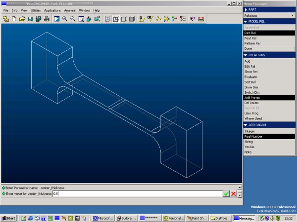
Within Pro/ENGINEER create parameters for all dimensions that will be varied during the design optimization. The steps are Relations -> Add Param -> Real Number, then give the parameter a meaningful name and assign a value to it. In the previous step it is also possible to assign an integer instead of a real number, however, this is only practical if all values for the parameter are exclusively integers. In our case I call the parameter center_thickness.
Creating a Relation
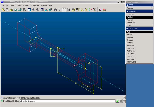
Next, the dimension of the beam needs to be associated with the above created parameter. Clicking on the beam will show all available dimensions and display them using Pro/E's internal numbering system (d0, d1, d2, etc.). Find the dimension number that determines the center thickness of the beam (here: d2) hit Add and use the input box to key in the relation (here: d2=center_thickness).
Tip: To close the input box hit Enter when the input box is empty


