Resources
Home
Step 3 - Model Setup
In Step 1 and 2 we have created a model of the flexure that we wish to optimize, now in Step 3 we need to prepare this model for the finite element analysis. Applications (from the tool bar) followed by Mechanica and Structure invokes the integrated mode of Pro/MECHANICA. Here we define everything necessary for the design optimization. Selecting Model lets us define the geometry to be analyzed.
Constraints
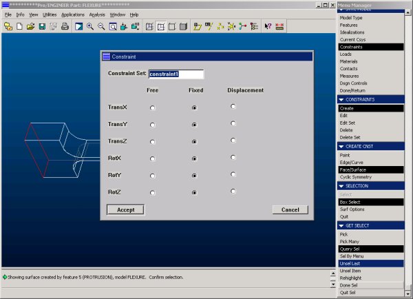
We will start with the constraints, i.e. how the flexure is held in place. To simulate the flexure's operation, we will constrain the left end completely, i.e. keep this surface completely from moving. Use Model -> Constraints -> Create -> Face/Surface and pick the face at the left end of the flexure. Hit Done Select to confirm your selection and use the constraint window to set the boundary conditions. We want to keep this surface from moving, so we constrain it in the X,- Y- and Z-direction. Solids (3-D elements) do not have a rotational degree of freedom (unlike 2-D or 1-D elements), so the settings for RotX, RotY and RotZ will have no effect on the analysis.
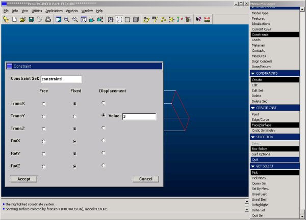
The right end we will constrain in the X- and Z- direction and impose a displacement of 3 mm in the Y-direction. Note that an analysis can only be defined with a single constraint set. If more than one feature needs to be constrained, the same constraint set (here: constraint1) has to be used.
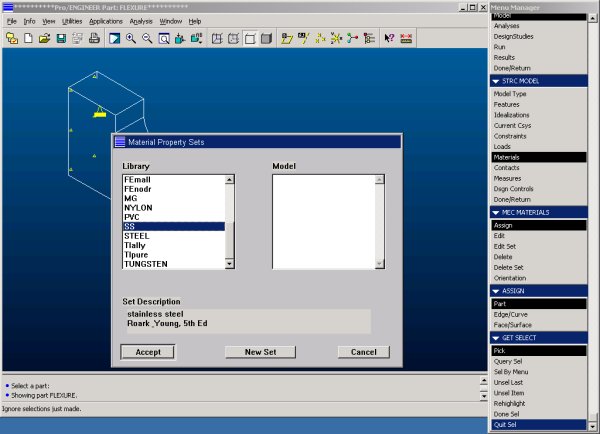
Material Properties
Next we need to assign material properties to our model. In this case we will make the flexure out of stainless steel. Pro/MECHANICA has a limited selection of pre-defined materials that we can choose from. Material sets not found will have to be created by ourselves, using the same unit system selected in step 1.
Note: For the N-mm-s system, the correct density will have to be given in tons per cubic millimeter to maintain the consistency of the units.
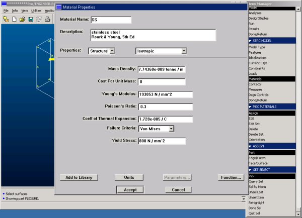
Accepting the material will open up the material property window.
Design Parameters
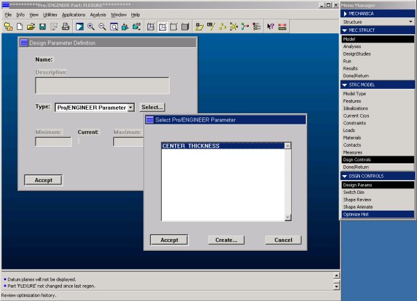
In order to use the design parameters set up in step 1, we first must make them available to Pro/MECHANICA. This is done through Model -> Dsgn Controls -> Design Params -> Create. The type of parameter needs to be set to Pro/ENGINEER. A window will pop up and show all available parameters.
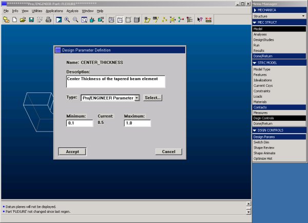
After the selection, the lower and upper limit for this variable will need to be set.
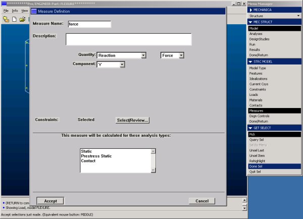
Measures
We can use MECHANICA also to determine the force required to displace the right side of the flexure by 3 mm. This is done by defining a measure which tracks the reaction at one of the two constraints.