Resources
Home
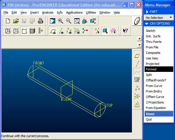
Formed Datum Curve
In this case, because the surface of the pin is cylindrical, creating such a feature is a little more involved. The two options available for a non-planar surface are to either a Formed or Projected a datum curve.
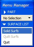
The surface onto which the datum curve is being formed is a solid surface. Therefore
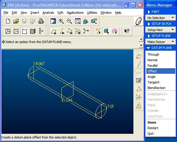
We will need to create a sketch plane that is located above the cylindrial surface. Here, the cylinder has a radius of 5mm and the sketch plane is been created as an Offset to TOP at a distance of 10mm.
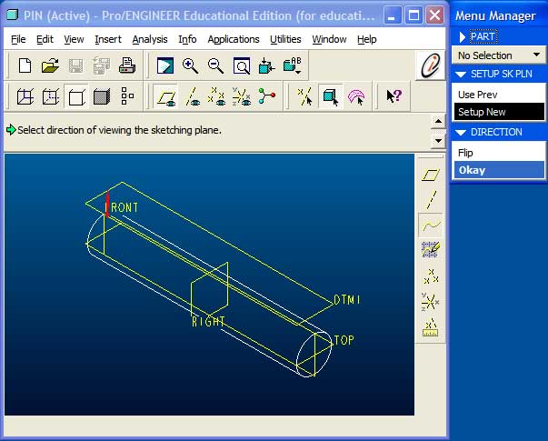
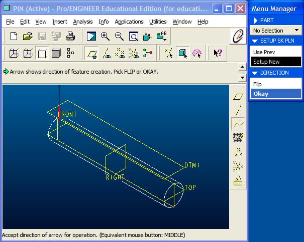
Select the direction of viewing such that it points towards the surface.
And also ensure that the direction of feature creation is pointing towards the surface.
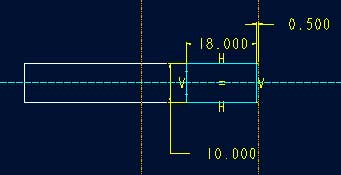
Sketch the outline of the datum curve that will define the surface region. Here, the surface region is intended to model the interface between the pin and the sleeve.
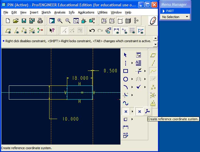
In addition to the curve, a reference coordinate system is required. It is recommended to place this coordinate system at a well defined location to eliminate the need for additional dimensions.
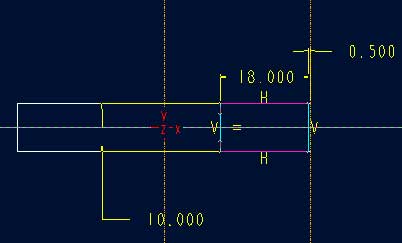
The finished sketch.
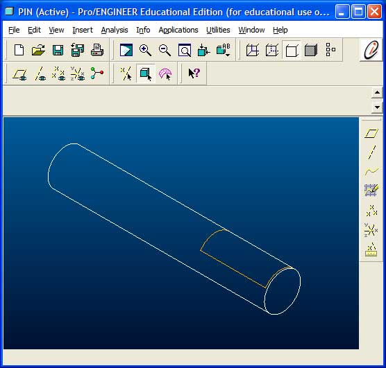
The formed datum curve on the cylindrical surface of the pin.
Repeat the previous steps to create the remaining datum curves and then launch Pro/MECHANICA.
Hint: Do not create defining features (datum curves) for more than one surface region at a time. Pro/MECHANICA will not be able to create the surface regions properly.