Resources
Home

Surface Regions
Applying loads and constraints to points or edge/curves very often results in stress concentrations and causes a model to converge with great difficulty only. As a result, it is generally recommended to use surfaces instead.
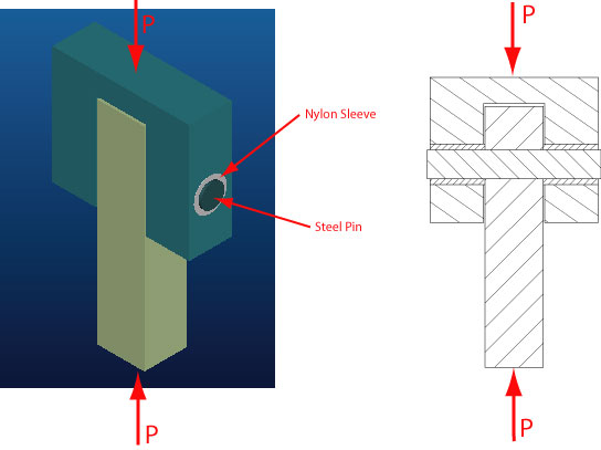
However, such a suited surface may not always be present. The pin joint shown below is such an example.
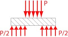
Using a Free Body Diagram (FBD), we can easily find the loads onto the pin as
The steel pin has a uniform diameter, resulting in a single outer surface. Hence, it is impossible to apply realistic boundary conditions and loads. The solution to this dilema is the creation of three surface regions that resemble the three distinct areas of the pin.
A surface region is available as a feature within Pro/MECHANICA and requires a feature describing its boundaries. While it is possible to sketch such a feature on the fly, it is probably easier to create the required feature within Pro/ENGINEER.
Step 1: Create formed datum curve
Step 2: Create surface regions