Teaching
Resources
Conceptual Machine Design Simplification Modeler for Rapid Machine Design (Patent Pending)
Shreyas Hoskere, M.S. University of Utah, May 2005
Analysis and objective evaluation of complex designs such as machine tools is difficult to perform during the conceptual design phase. CoM-SiM is a 3D parametric sketcher tool which aids an engineer to set up 3D sketches or 'stick figures' of mechanical devices and mechanisms very quickly. The user can sketch the mechanical design in CoM-SiM like sketching on paper.
All elements sketched are idealized finite elements and their element type can be defined or changed at anytime during the sketching process. All sketches are converted to FE code readable by ANSYS FEA package. CoM-SiM has a 'materials' database and a 'beam section' database to apply appropriate properties to the sketched elements when needed. To especially accommodate precision machine tool design, it also contains a standard 'Ballscrew' and 'Bearing' database with built-in stiffness calculators to allow sketching and evaluation of precision machine tools with their bearing and ballscrew systems.
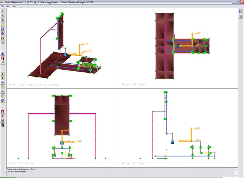
The GUI is a menu and toolbar driven interface which implements user inputs from a standard mouse and keyboard. Built for the Microsoft Windows platform and implementing smooth OpenGL graphic libraries, the GUI incorporates a four-split window which displays a constantly updated, standard three orthographic views and a projection view of the 3D model. The model can be sketched on any of the four views with seamless switching between views during sketching. All the sketching is directly drawn in 3D using an innovative 'parallel to view plane' method.
The GUI also implements several graphical cues to view the 3D (wireframe) sketches very intuitively. The parametric 3D sketching allows existing concepts to be modified very quickly in order to explore different design configurations, making this tool much more versatile than a paper sketch.
Videos Modeling and analyzing a frame with four legs. The video uses modeling across different views for fast modeling. SketchingAndAnalyzingFrameWithFourLegs.avi Modeling a ball screw as a spring and assigning properties from a database. Complicated mechnical elements such as ball screws, which consist of a large number of rolling elements are simplified by a spring, whose properties are assigned from a database. BallscrewForm.avi Modeling a bearing as a spring and assigning properties from a database. Bearings a complex mechanical elements that consists of a large number of rolling elements. In Com-Sim, a bearing is simplified with a spring whose properties are assigned from a database. BearingForm.avi The sketch plane is automatically defined by selecting a single point. In Com-Sim, the sketch plane does not need to be defined explicitly. Instead, the sketching plane is automatically defined by selecting an exisiting node. The sketch plane is then created that contains the node and is parallel to the view orientation. If no node is selected, the sketch plane goes through the origin and is parallel to the view of the window. PlanePointMethod.avi Modeling and analyzing a 5-axis machine (Star Tool Grinder). A complex machine tool sich as the STG (see link for details) can be greatly simplified in Com-Sim and analyzed using commercial finite element software (e.g. Ansys). STGAnalysisInANSYS.avi Publications:
E. Bamberg, S. Hoskere (2005). CoM-SiM - conceptual machine design simplification modeler. In: Proc. 2005 Euspen Conf., Montpellier, France, May 8-11, 2005 (2), pp. 417-420.